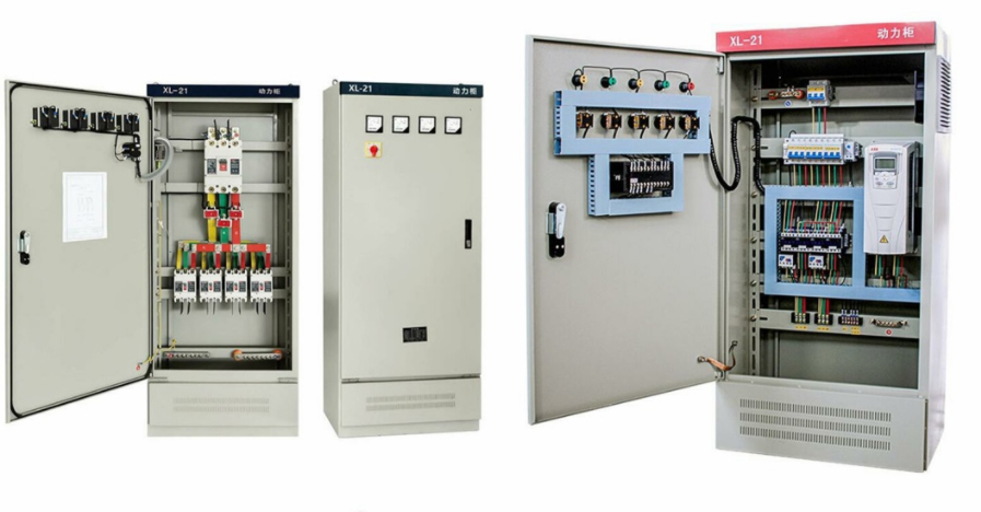
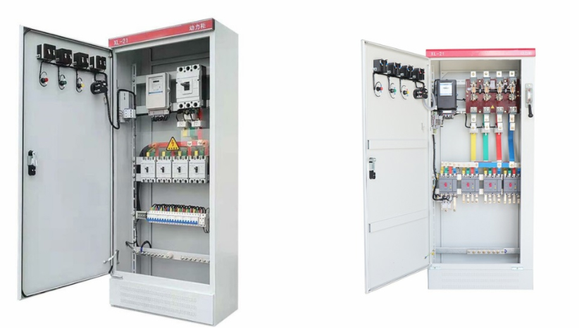
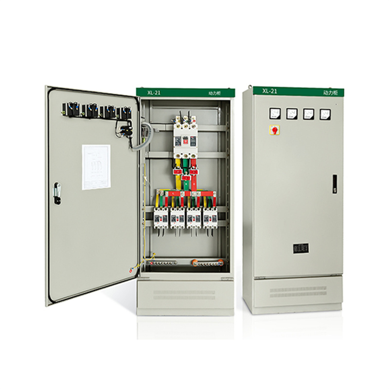
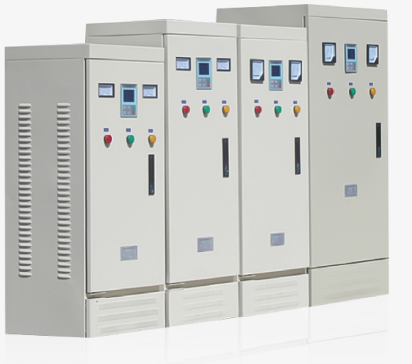
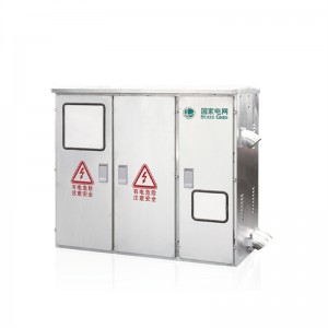
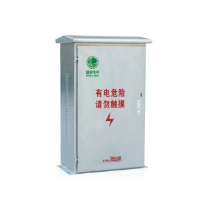
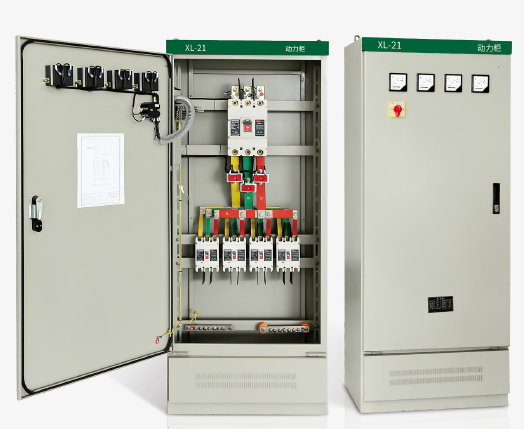
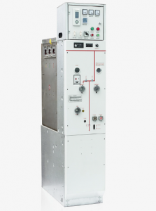
Distribution cabinet jp3 phase electrical distribution cabinet
Model description

Features
1. Main electrical performance shall completely comply with regulations of IEC60439-1:1992, GB7251.1-1997.
2. The auxiliary circuit has functions of local/remote, remote, automatic control and in-site/remote, remote control switch. The contractor can adopt DC protection.
3. Receiving the main switch has optional protection of in start trip and pyromagnetic trip. Can cancel instant protection for matching next class main-switch, avoid skip-class tripping, and has functions of motor/manual operation and automatic switch.
4. Main switch of the feeding circuit has the protection of instant trip and pyromagnetic trip. Can add fault protection if customer required.
5. The motor control circuit has the protection of short-circuit instant. overload, Under voltage release and phase-break.
6. Ammeter and voltage meter for the incoming circuit.
Environment condition
1. Ambient air temperature: -5℃~+40℃ and the average temperature should not exceed +35 in 24h.
2. Install and use indoors. Altitude above sea level for operation site should not exceed 2000M.
3. Relative humidity should not exceed 50% at max temperature +40. Higher relative humidity is allowed at lower temperature. Ex. 90% at +20. But in view of the temperature change, it is possible that moderate dews will produce casually.
4. Installation gradient not exceed 5.
5. Install in the places without fierce vibration and shock and the sites insufficient to erode the electrical components.
6. Any specific requirement, consult with manufactory.
Technical parameters of main equipments
Knife melting combination switch
| Type | Rated current(A) | Melt rated current (A) | Remarks |
| HR3-400/34 | 400 | 150. 200.250.300.350.400 |
Current transformer
| Type | Rated current(A) | Secondary current(A) | Remarks |
| LM-0.5 | 75. 100.150.200.300.600 | 5 |
Fuse protector
| Type | Fuse protector | Melt rated current(A) | Remarks |
| RL1-15 | 15 | 2.4.5.6.10.15 | |
| RL1-60 | 60 | 20.25.30.35.40.50.60 | |
| RL1-100 | 100 | 30.40.50.60.80.100 | |
| RL1-200 | 200 | 80.100.120.150.200 | |
| RL1-400 | 400 | 150.200.250.300.350.400 |
A/C contactor
| Type | Rated current(A) | Attraction coil voltage(V) | Remarks |
| CJ10-10 | 10 | AC 110. 220. 380 | |
| CJ10-20 | 20 | ||
| CJ10-40 | 40 | ||
| CJ10-80 | 80 | ||
| CJ10-150 | 150 |
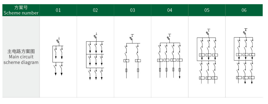
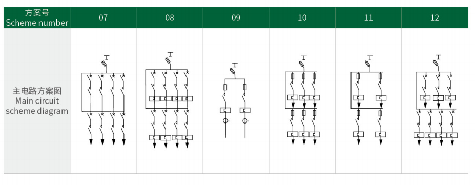
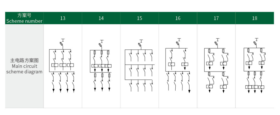
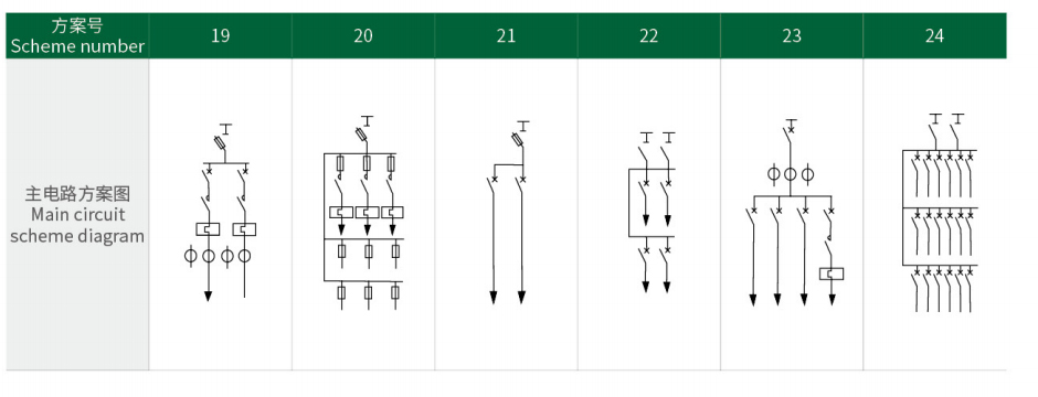
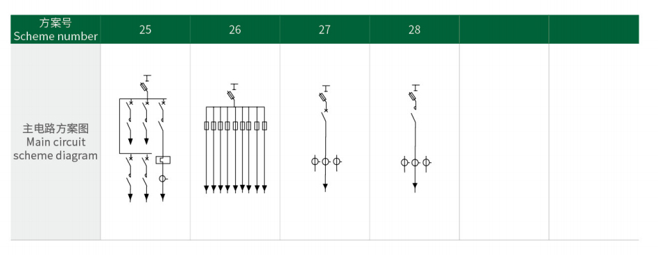
Main circuit scheme diagrams
Product photo
